- +38-067-01-07-001
- Ukraine, Odessa, 16a Malinovskogo street, ap 301, 65059
- elecran
- support@elecran.com.ua, elecran@elecran.com.ua
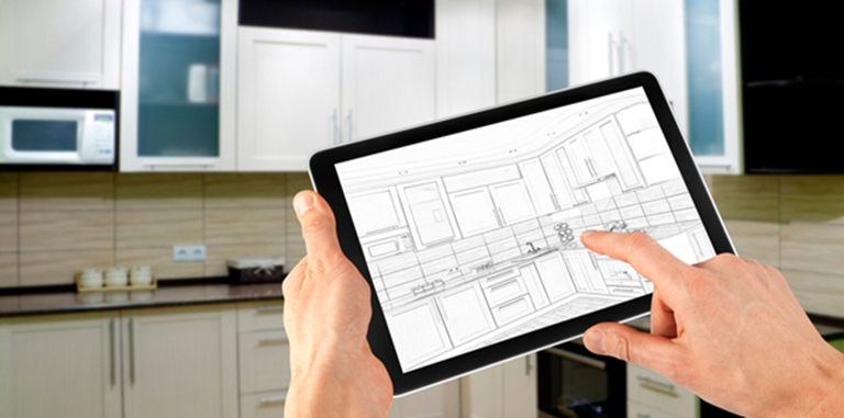
Software for parametric furniture designing
The piece of furniture may include sheet parts, profiles, bent parts, worktops, multilayer parts, composite part, edge banding, furniture accessories and fastener.
You work in 3D-view with real furniture objects
After approving a design, you can automatically generate:
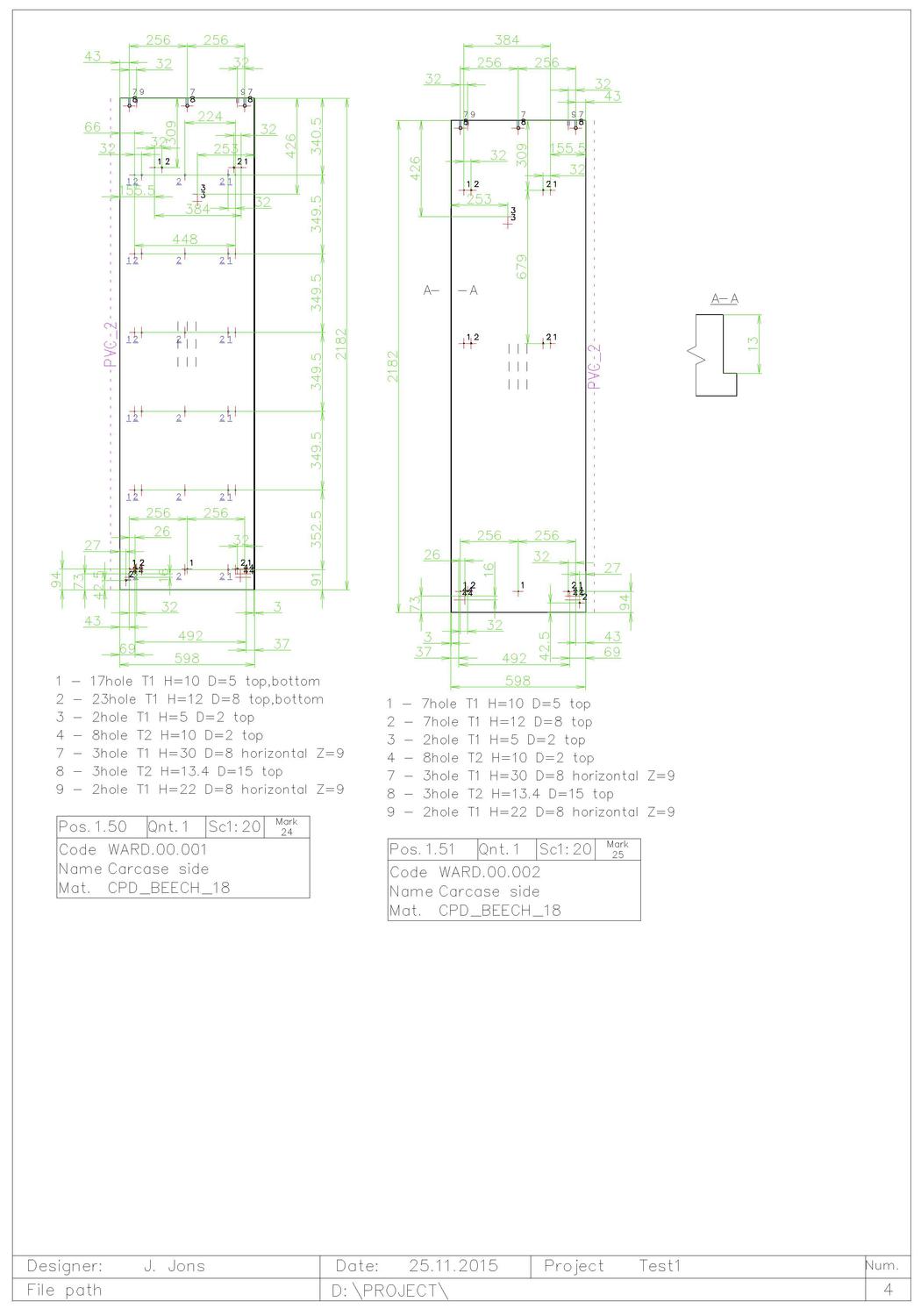
- 2D working drawings of the parts, profiles, bent parts;
- Assembly drawing of product;
- Manufacturing reports and price-list;
- Cut-list for cut planning software;
- CNC programs for woodworking machines.
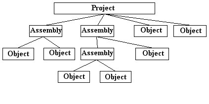
Project structure
The project may include independent parts and assemblies.
The assembly may include parts and other assemblies. The quantity of objects included in a project or in an assembly not limited. The assembly not included in any assembly is a product. The examples of products are table, bookcase, pantry etc. The examples of sub-assemblies are drawer, set of shelves, desk cupboard etc. The scheme of project structure is present bellow.
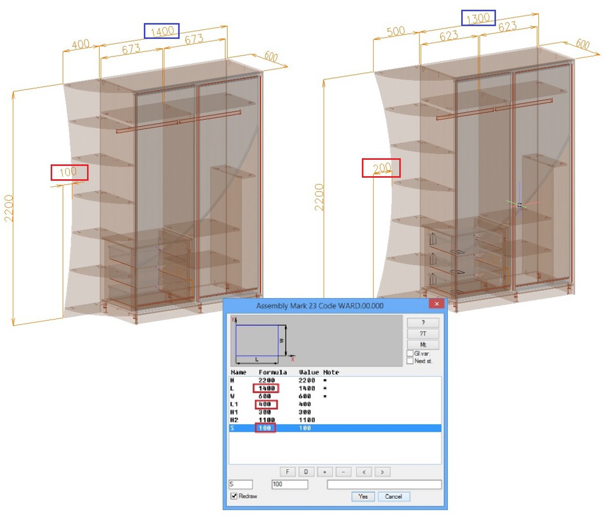
Every part and assembly may have parameters, created by user. Parameters may define object dimensions, object position and object shape therefore you can create family of products using one model.
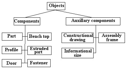
Parts
Creating of parts
There are next types of part in 3D-Constructor:
- Sheet part (one layer part and multilayer part)
- Bent part (one layer part and multilayer part)
- Worktops
- Extruded part (part with variable thickness)
- Door (Flat door, MDF door, Framed door)
- Tamburat (it is composited part, which include some parts and fastener)
The ways to create parts:
- utilizing typical parametrical parts (the base of parametrical parts supplied by producer)
- creating and placing parts by specifying points of existing objects
- drawing part form in Construction Drawing (it is a special program tool, to draw parametric forms yourself)
- copying of any existing part
- import parts from AutoCAD project (only solids may be imported)
Part editing
There are some operations to edit part:
- parametric operation to edit part contour (rounding, chamfer, cut on a corner, opening etc.)
- drawing and replacing part shape with Constructional Drawing (it isa special program tool)
-drawing part shape with CAD primitives (you can use a polyline, line, arc to draw a shape of opening or a shape of part contour that will be joined to part )
- cutting part or profile by another part or profile or bent sheet.
Assembly creating
The assembly is a special object that executes two functions in the project:
-it logically combines some objects in one product (some piece of cupboard usually are included in one assembly-product)
-it gives user anchor points and edges that may be used to create parts easy and quickly.
When you create a new assembly its variables environment is automatically generated. You may use any of assembly variable to define part dimensions, operation parameters or object position. The user may edit the assembly variables by oneself, determining mathematical and logical dependences.
There are two designing technology “from top to down” and “from down to top”. In the first case you create assembly (define its shape and dimensions) determine its variables and then you create objects included in the assembly. In the second case you create objects and then combine them in the assembly
There are some types of assembly in the project.
-assembly product
-typical assembly (usually it is a part of product, that can be inserted in different products, for example a set of shelves or unit template)
-drawer
-framed door
-Tamburat (composed part)
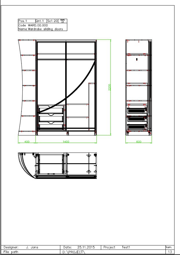
2D-drawings and assembly drawings
2D working drawings of objects and assembly drawings can be automatically generated with program. The program allow to create multi-views drawing. You may create some views for one object with different information. It is possible to display bellow mentioned information on the view.
Cutting dimensions
Overall dimensions
Material direction
Properties “rotate in pattern” when cutting material
Edge of part covered with edge banding
Edge of part milled with cutter profiles
Holes for inserted fittings
There are some dimensional styles for the drawings (standard, from one base, grid, not all dimensions).
The assembly drawings include orthogonal, isometric and exploded views. You can copy and edit existing views (delete some objects from the view, insert leaders, align leaders). To get some steps of product assembling it is comfortable to copy and edit the exploded view.
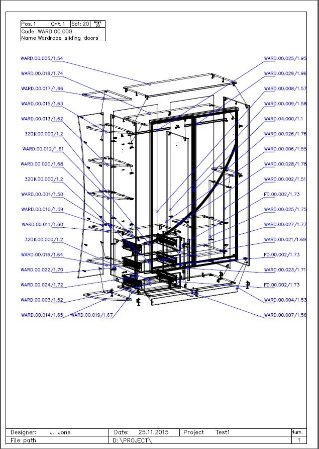
The drawings are associated with 3D-model. It means that drawings will be automatically updated if you edit the 3D-model. All drawing settings may be preset in drawing styles, defined by user
Manufacturing reports and price-list
The report module allows you to determine a report template flexible. It is possible to define:
-what information should be present in the report
-report form (the order of the columns in the report, columns width, text font, header and etc.)
-multiple sort (for example at the first by material, at the second by code)
-Filters (for example, only materials which have “MDF*” in the code will be included in the report)
-All objects may be separated by products.
The program generates:
-Parts report, Doors report, assemblies report
-Jobs report
-Materials and fittings report
-Cutlist report
-Other reports which you will invent
Jobs report
The program provides automatic calculation and accounting in the price-list:
-Quantity of holes with defined parameters (to calculate drilling and assembling)
-Length of milling grooves
-Length of saw grooves
-Length of manual edge banding strip
-Length of machine edge banding strip
-Length of angular cut
-Length of external contour routing
-Parts square (to calculate primering , spraying, staining, etc)
-Parts perimeter (to calculate cutting)
All changes done in jobs are immediately reflected in the price-list and in the bid of the project.
Any report may be easy exported to Microsoft Excel.